Sifarişçilər


The string is a Lenovo internal PCB part number, often found silkscreened near the RAM slots or under the M.2 SSD shield. It breaks down as:
Before we dive into the specifics of the 17IPS72 schematic, it's essential to understand what a schematic is. A schematic, also known as a circuit diagram, is a visual representation of an electronic circuit. It uses standardized symbols and notations to illustrate the components, connections, and relationships between various parts of a circuit. Schematics are used to design, build, and troubleshoot electronic devices, making them an indispensable tool for anyone working with electronics.
even after the TV is unplugged. Always discharge the main filter capacitor before touching the board or using a multimeter in resistance mode. Where to find the Schematic?
Check for burnt components around the PWM controller, particularly MOSFETs in the standby circuit.
: Trace the LED+ and LED- lines to diagnose "no backlight" issues.
Strengths (practical):
The Vestel 17IPS72 is a highly integrated, single-board Power Supply and LED Backlight Driver. The circuitry is split into three primary stages: the Input & Power Factor Correction (PFC) stage, the Resonant Switching/Main Power Generation stage, and the LED Driver block.
: Look for bulging or leaking electrolytic capacitors, as these are a common point of failure in Vestel boards.
Provides +12V DC (Main board / Standby power) and +24V DC (Audio / Peripheral power). Common Board Revisions: 17IPS72-R3 and 17IPS72-R4 . Block Diagram of Circuit Stages
Understanding the 17IPS72 schematic diagram is essential for component-level repair technicians. Diagnosing issues at this level saves consumers and repair shops from purchasing expensive replacement boards. This guide breaks down the core sections of the 17IPS72 architecture, identifies common failure points, and outlines systematic repair steps based on technical community findings. Core Structural Sections of the 17IPS72 Architecture
Legitimate sources (avoid malware-ridden free download sites):
: DC-DC Boost controller IC, LED driver MOSFET, and current sensing resistors.
The board includes multiple regulators to convert the high-voltage DC into usable low voltages, such as , for the TV's main board and audio stages. LED Driver:
: Provides a critical 5V-STBY rail; a lack of this is a common failure point often discussed on repair forums like Elektroda .
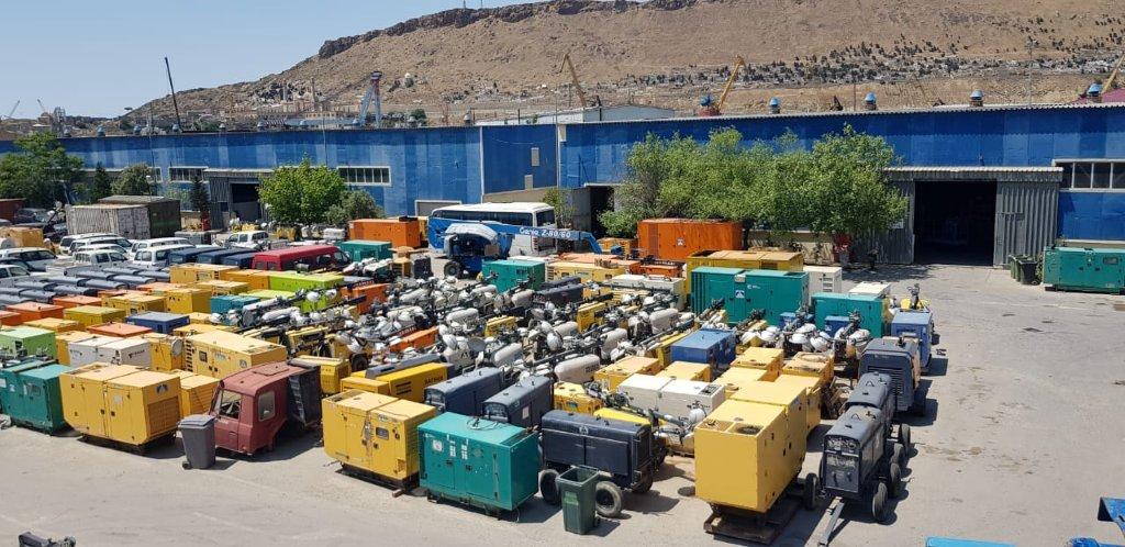
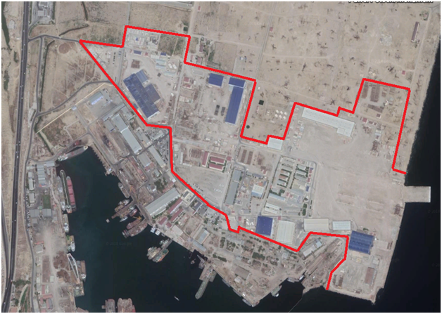
Obyektlər
Son işlərimiz
Layihələr
AZƏRBAYCAN
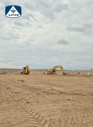
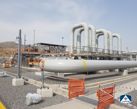
BP-nin “Sunrise” (Şəfəq) SPP (günəş elektrik stansiyası) layihəsi — Cəbrayılda həyata keçirilən 288 MWp (240 MW AC) gücündə böyükmiqyaslı fotovoltaik enerji layihəsi
2025
Dünya standartları
GÜRCÜSTAN
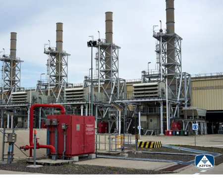
Mülki, Struktur, Mexaniki İstehsalat, Mexaniki Tikinti, ICE təminatı layihəsi
2021
GÜRCÜSTAN
Gürcüstan Respublikası ərazisində istehsalat, tikinti, mülki obyektlərinin inşaatı, elektrik avadanlıqlarının və cihazlarının təmiri işləri
2023
Dünya standartlarına cavab verən AZFEN MMC
AZFEN MMC 1996-cı ilin yanvarında Azərbaycan Respublikası Dövlət Neft Şirkəti (60% sahiblik hüququ ilə) və TEKFEN İnşaat və Təsisat A.Ş. (40% sahiblik hüququ ilə) tərəfindən təsis edilmişdir.
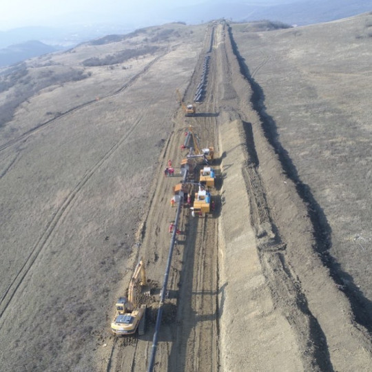
Məqsədimiz neft şirkətləri üçün yüksək səviyyəli tikinti və mühəndislik işlərini həyata keçirməkdən ibarətdir. Təcrübə və müasir texnologiyaların tətbiqi bizə Xəzər regionunda neft şirkətlərinə misilsiz xidmət göstərmək imkanı vermişdir. Biz irihəcmli neft layihələri üçün boru kəmərlərinin, platformaların və terminalların tikintisini həyata keçirmişik. Bacarıq və təcrübəmizlə yanaşı, sağlam və təhlükəsiz iş şəraitinə böyük əhəmiyyət veririk.
Hal-hazırda AZFEN fəaliyyətini dünya miqyasında genişləndirməyə çalışır.
The string is a Lenovo internal PCB part number, often found silkscreened near the RAM slots or under the M.2 SSD shield. It breaks down as:
Before we dive into the specifics of the 17IPS72 schematic, it's essential to understand what a schematic is. A schematic, also known as a circuit diagram, is a visual representation of an electronic circuit. It uses standardized symbols and notations to illustrate the components, connections, and relationships between various parts of a circuit. Schematics are used to design, build, and troubleshoot electronic devices, making them an indispensable tool for anyone working with electronics.
even after the TV is unplugged. Always discharge the main filter capacitor before touching the board or using a multimeter in resistance mode. Where to find the Schematic?
Check for burnt components around the PWM controller, particularly MOSFETs in the standby circuit. 17ips72 schematic
: Trace the LED+ and LED- lines to diagnose "no backlight" issues.
Strengths (practical):
The Vestel 17IPS72 is a highly integrated, single-board Power Supply and LED Backlight Driver. The circuitry is split into three primary stages: the Input & Power Factor Correction (PFC) stage, the Resonant Switching/Main Power Generation stage, and the LED Driver block. The string is a Lenovo internal PCB part
: Look for bulging or leaking electrolytic capacitors, as these are a common point of failure in Vestel boards.
Provides +12V DC (Main board / Standby power) and +24V DC (Audio / Peripheral power). Common Board Revisions: 17IPS72-R3 and 17IPS72-R4 . Block Diagram of Circuit Stages
Understanding the 17IPS72 schematic diagram is essential for component-level repair technicians. Diagnosing issues at this level saves consumers and repair shops from purchasing expensive replacement boards. This guide breaks down the core sections of the 17IPS72 architecture, identifies common failure points, and outlines systematic repair steps based on technical community findings. Core Structural Sections of the 17IPS72 Architecture It uses standardized symbols and notations to illustrate
Legitimate sources (avoid malware-ridden free download sites):
: DC-DC Boost controller IC, LED driver MOSFET, and current sensing resistors.
The board includes multiple regulators to convert the high-voltage DC into usable low voltages, such as , for the TV's main board and audio stages. LED Driver:
: Provides a critical 5V-STBY rail; a lack of this is a common failure point often discussed on repair forums like Elektroda .

Ümummilli lider
Prezident

Birinci Vitse-Prezident